0 items
Calibration & Testing Rogowski Coils
Coils are calibrated to measure their mutual inductance to a conductor threading the coil. Equally important is to test the coil for cross-talk to adjacent conductors.
Calibration: Mutual Inductance
Coils are individually calibrated using a specially designed bridge. The current measured by the coil is compared with the current in a high-precision resistor to a resolution of about one part in 10,000. The calibration data are used to calculate the mutual inductance (M) between the coil and a single conductor threading it. For a flexible coil the mutual inductance usually relates to one wrap of the coil round the conductor. If the coil is wrapped ’n’ times round the conductor the mutual inductance should be multiplied by ’n’. Similarly if the conductor is wrapped ‘m’ times round the coil the mutual inductance is multiplied by m.
The output from a coil when it encircles a current is given by: Vcoil=-MdI/dt where I is the (time-dependent) current.
For convenience we sometimes also quote the coil output in terms of a particular current and frequency e.g. output for 1kA at 50Hz or 60Hz.
Calibration: Coil and Integrator
The combination of a coil and an integrator provides an output voltage waveform which represents the current waveform. For calibration purposes this output can be compared directly with the voltage across a precision resistor. The two voltages are measured and compared to a high degree of precision using a frequency response analyser which computes their ratio directly. The integrator is then adjusted to give the required calibration. This technique is capable of an uncertainty better than 0.1%. It can also be used to measure the amplitude and phase response of complete systems as a function of frequency.
Testing Coils
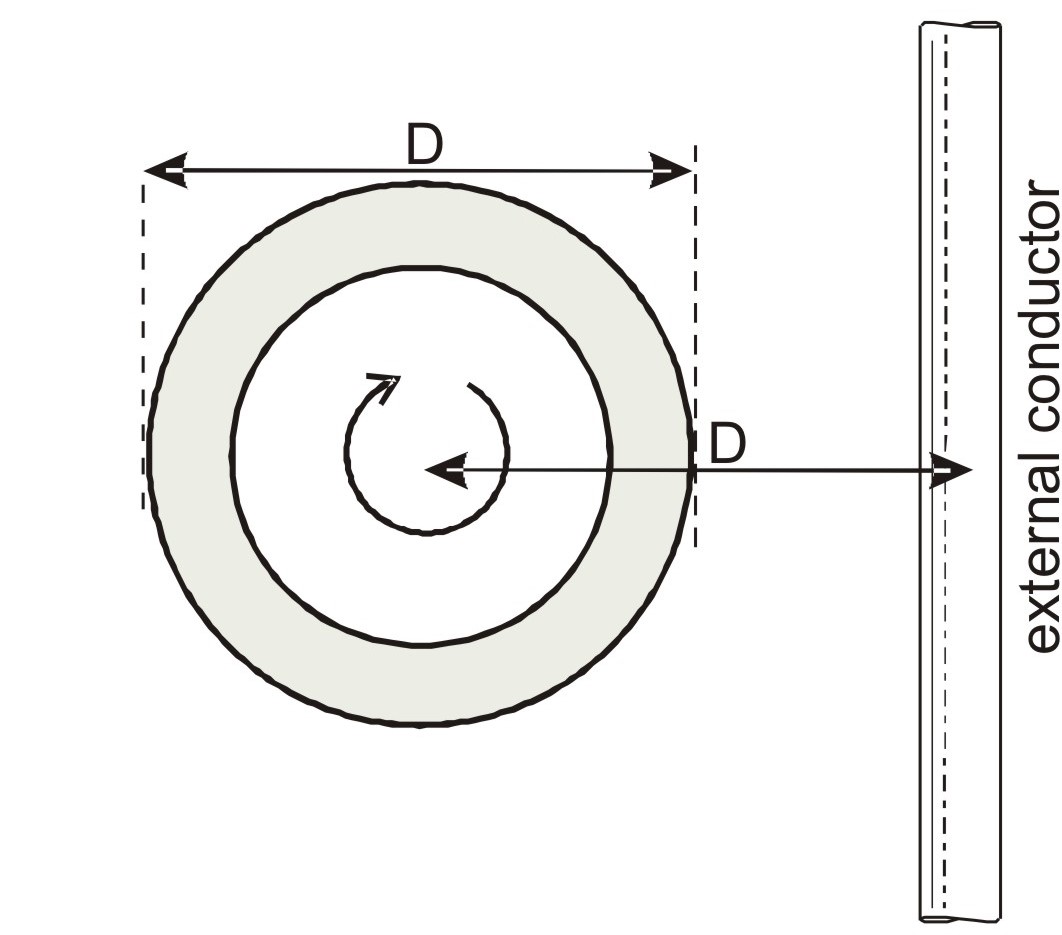
Coils are tested to check how sensitive they are to ‘cross-talk’ or pick-up from current-carrying conductors that do not thread the coil and from other sources of external magnetic fields. This is done by placing the conductor alongside a current-carrying conductor and comparing the output of the coil with the output that would be obtained with the coil encircling the conductor.
The degree of rejection is expressed as a percentage ratio. Theoretically, for a perfectly uniform winding , the pick-up should be zero. Inevitably there will be small winding defects and measurement of the pick-up ratio is used as a quality check.
The coil is usually placed at a distance of one diameter (D) away from the conductor as shown in the figure. The coil is turned in all orientations to find the maximum pick-up. For a rigid coil wound on an accurately-machined former the ratio is significantly less than 0.1% for any orientation of the coil. For flexible coils it is less than 1%.

Perpendicular Test

Parallel Test
Share this page